MARTETIC MODULAR · LSF · TIMBER FRAME

You build the module. We deliver the foundation interface.

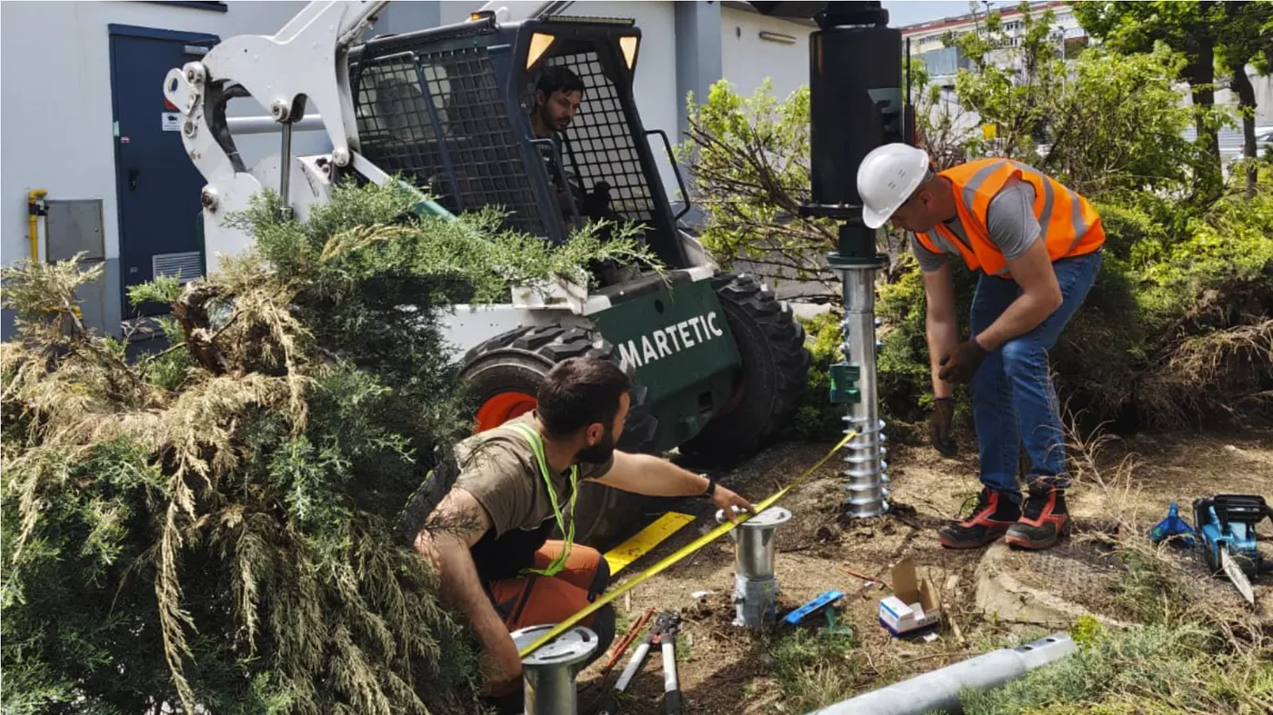
A foundation system designed around factory-built construction: repeatable support geometry, mechanised installation, site-specific screw selection and a clean handover before the structure arrives.

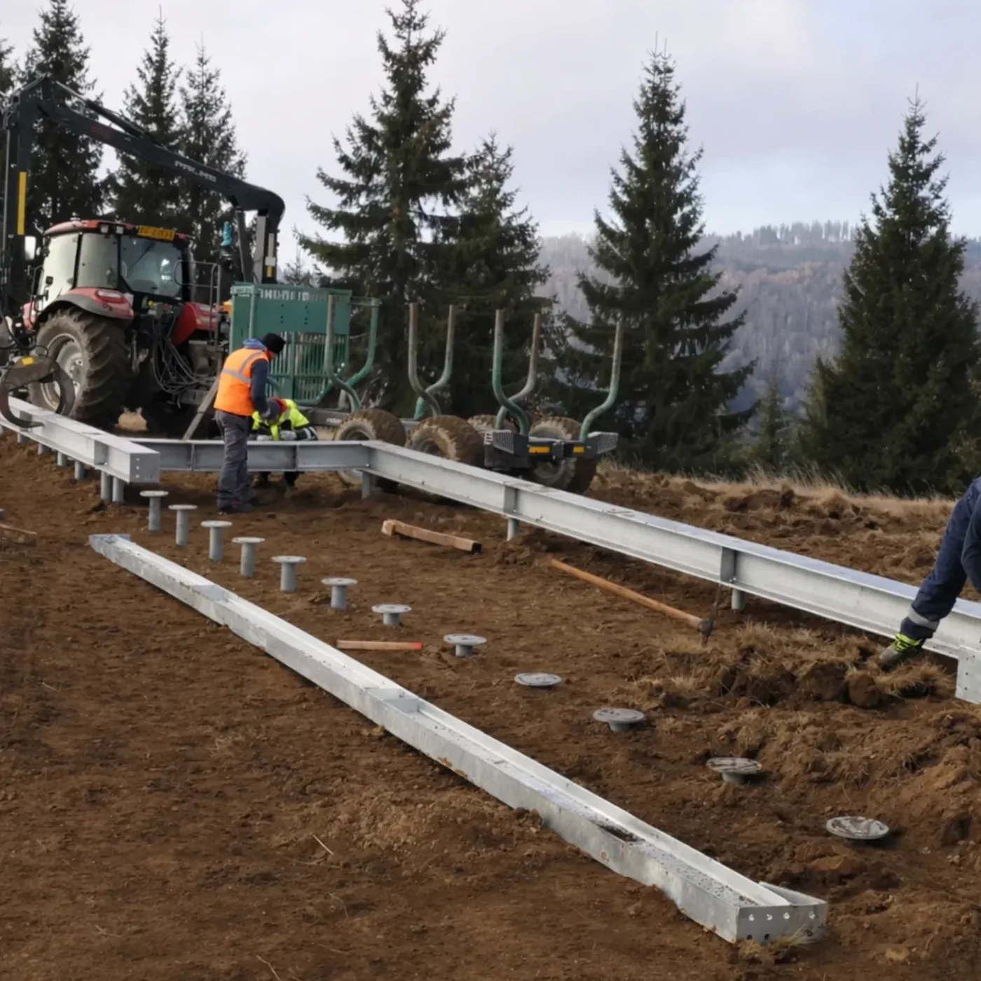
MARTETIC wooden modular house project
Real project · timber structureFoundation and platform integrated with the building.
Factory precisionsupport points planned before site delivery
Site adaptationproduct / depth selected per site
Repeatable handoverposition · level · interface · documentation
The principle: standardise the connection to the building; adapt the foundation below it to the real loads, soil and site. Do not standardise one screw for every project.
01 / WHY THIS FITS MODULAR CONSTRUCTION

Factory-built speed only works if the site is ready.

The modular market competes on controlled production, shorter on-site assembly and predictable quality. The foundation is one of the last interfaces that can still delay the module, introduce tolerance problems or create extra trades on site.

⌖

Foundation ready before delivery

The support grid can be installed and checked before the module or wall system arrives.

±

Tolerance strategy

Position, level and the adjustment zone at the connection are planned as part of the interface.

↗

Slope & variable terrain

Point foundations can reduce some platform / excavation work when the structural concept allows it.

↻

Repeat the process

One model family can use one building-side interface while the foundation below is adapted site by site.

02 / CHOOSE YOUR PERSPECTIVE

The same foundation system solves a different problem for each project team.

BEST STARTING INPUT

03 / THE KEY B2B IDEA

Standardise the interface. Adapt the screw.

A modular manufacturer should not redesign the building chassis every time the soil changes. The better system is to keep the building-side support geometry stable and adapt the foundation product, length, extension or local steel connection below it.

Illustrative 12-point modular support grid

Based on a MARTETIC engineering-development concept for a compact LSF module. This is not a universal prescription.

≈ 5.6–6.25 m≈ 3.125 m
The point count, spacing and adapter are confirmed by the building loads and final structural design. Heavier configurations, larger openings or weaker ground may require another grid or other products.
SAME BUILDING INTERFACE · DIFFERENT SITE

See how the foundation can change below the same module.

The examples below describe the design logic, not an automatic product selection.

04 / SITE SCENARIOS

A good modular foundation starts by saying where it fits — and where it does not.

Rule: the site does not become suitable just because the building is lightweight. Soil, loads, lateral actions, corrosion, access and the connection to the structure still need to be checked.
05 / PRODUCT FAMILIES FOR THE FIRST DISCUSSION

Start from the building. Then select the foundation family.

M76

Light modular / timber frames

A starting family for lighter platforms, timber frames and small modular structures when the loads and ground allow it.

Typical interface: flange-based connection · exact model confirmed by project
M89

Modular houses & LSF

The MARTETIC product registry identifies the M89 family for modular houses, LSF and residential structures. One confirmed M89 configuration uses a Ø220 × 12 mm flange and M24 central connection.

Compression + uplift verification are relevant for modular / LSF projects
V89

Modular depth

Tip + extension(s) + structural top connection can be used where the load-bearing layer is deeper and a modular configuration is appropriate.

Useful for site variability · configuration verified at real depth
V114 / PROJECT

Higher-load or special conditions

For larger reactions or special site conditions, a heavier project-specific family may be considered. Product documentation and exact configuration are confirmed in the project offer.

No universal tonnes-per-screw promise
The screw family, length, extensions, number of points and connection are not selected from building area alone. They depend on support reactions, soil profile, groundwater, spacing, installation conditions and the type of loading.
06 / CONVENTIONAL VS SCREW FOUNDATION

Compare complete construction sequences — not one material with another.

CONVENTIONAL PATH

Shallow concrete foundation / platform

  • excavation and formation level
  • formwork / reinforcement / concrete as required
  • curing and follow-on sequence
  • backfill / platform / drainage coordination
  • good solution when technically and commercially rational
SCREW FOUNDATION PATH

Point foundations + structural interface

  • survey / set-out of support points
  • mechanised installation to selected configuration
  • position / level / verticality control
  • adapter / steel frame / direct connection as designed
  • module can arrive after foundation handover
07 / PARTNER WORKFLOW FOR A MODULAR MANUFACTURER

Build the foundation interface once. Repeat the process project by project.

01

Standard model

GA, chassis / wall support geometry, module mass, structural concept.

02

Interface library

Support grid, adapter zone, level strategy and building-side connection.

03

Site intake

Location, soil / geo, slope, utilities, access and delivery date.

04

Foundation install

Product selection, set-out, mechanised installation, level and agreed records.

05

Module delivery

The manufacturer arrives to a defined support interface instead of an unfinished foundation problem.

08 / THREE WAYS TO WORK WITH MARTETIC

From products only to a foundation ready for the structure.

01

Products only

For builders, installation partners and companies with their own site teams.

  • selected products / components
  • applicable product documents
  • transport if contracted
02

Products + installation

For the manufacturer that wants a controlled support grid delivered on site.

  • set-out and mechanised installation
  • alignment / level control
  • installation records / handover as contracted
03

Complete foundation interface

For projects where the manufacturer wants the site prepared for the next construction step.

  • local earthworks / geotextile / aggregate where included
  • steel frame / custom connection pieces
  • logistics and optional testing scope
09 / REAL MARTETIC PROJECTS

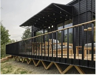
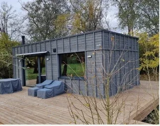
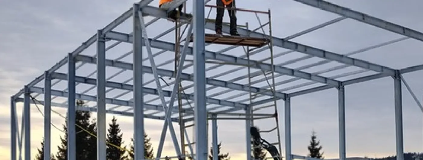
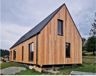
The useful proof is in the interface between ground, foundation and structure.

10 / WHY MARTETIC

Not just a screw supplier.

MARTETIC was built around lightweight construction, modular buildings and steel structures. The offer can combine product selection, mechanised installation, site preparation, structural connections, logistics, documentation and contracted verification.

MECHANISED

Equipment selected for the project

Installation equipment and reducers are selected by diameter, depth, ground, access and required torque.

CONTROLLED

Position, level & verticality

The support points are installed against a set-out plan and checked during execution.

TESTABLE

Compression / uplift testing available by project

For modular and LSF projects, representative axial testing can be included when required by the designer, beneficiary or contract.

DOCUMENTED

Product & installation records

Applicable product documents, traceability, installation records and test reports are defined in the contracted scope.

11 / PROJECT INTAKE

Six inputs are enough for a useful first conversation.

Do you have these?

0 / 6
12 / BUILD A REPEATABLE FOUNDATION INTERFACE

Send us one standard model.

We can start by defining the support-grid and foundation-interface logic for one of your models. Then each future site becomes a controlled adaptation of the foundation below that interface — not a new discussion from zero.

MARTETIC · NZEB GROUP SRL

+40 720 452 788

martetic@gmail.com

martetic.com


Best fit:

• modular house manufacturers

• LSF / Timber Frame / SIP builders

• cabin / glamping / resort developers

• container and technical-module manufacturers

Technical, legal and market basis used to build this presentation
  • MARTETIC 2026 product catalogue and product registry: M-family applications, modular systems, connection principles and project examples.
  • MARTETIC axial-testing catalogue: modular / LSF projects, compression / uplift testing and project-specific testing logic.
  • MARTETIC LSF engineering-development documents: illustrative support-grid and standard-interface concept; explicitly not presented as a verified universal design.
  • Law no. 50/1991 — authorisation of construction works
  • Law no. 372/2005 — energy performance of buildings
  • Market research reviewed Romanian modular, LSF and timber-frame manufacturers and current European construction / tourism indicators to understand client priorities; competitor names are intentionally omitted from the client-facing presentation.